Introduction
The standard vertical import template was created as a simple, user-friendly way of importing spec plans from other systems or by hand using Microsoft Excel. The template has been written to make it easy for a normal user to quickly create spec plans that can be imported into QC-Gage either individually or via a group of files in a folder.
Creating Files for Import
QC-Gage’s import tool expects a tab-delimited ASCII text file. You can quickly create this type of file in Microsoft Excel by filling out the template spreadsheet (attached) and saving the file as a tab-delimited .txt file.
To create the files to import, you can either generate them in Excel and save them as tab-delimited ASCII text files or create an export from another system that creates the ASCII files directly. Each spec plan you plan to create this way should have a corresponding tab-delimited text file that describes the fields in the “General Template Definition” section below.
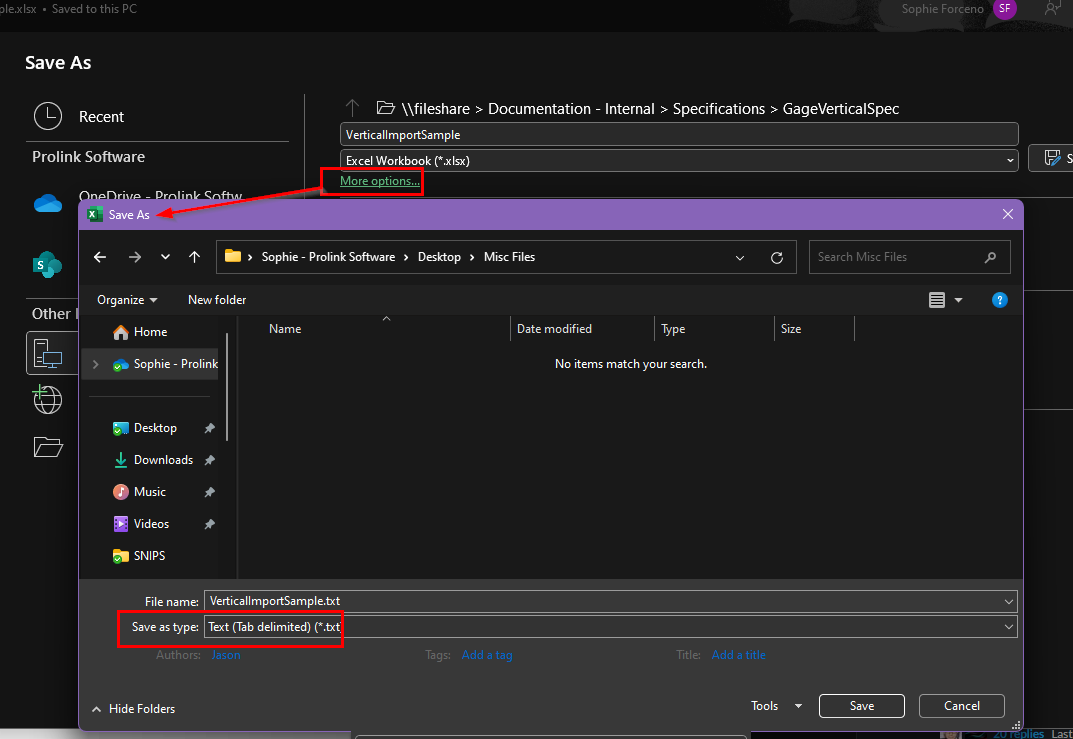
To save an Excel spreadsheet as a tab-delimited text file:
- Go to File > Save as….
- Select “More Options…” (appears under the file name and file type selectors)
- In the Save as… file browser that opens, set the “Save as Type” to Text (tab delimited) (*.txt)
- Click the Save button to save a .txt file that QC-Gage will import
Next, in QC-Gage, choose File > Create Spec Plan from Import > Import from Prolink Standard Format.
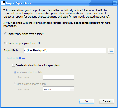
On the Import Spec Plans screen (above), specify whether you wish to import an individual .txt file or a folder full of .txt files (for multiple spec plan imports). You can also choose to create shortcut buttons in QC-Gage for the imported spec plan(s).
When you’re ready to import, choose OK, and QC-Gage will read all files specified and create spec plans for each file found.
General Template Definition
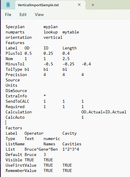
The template consists of three sections: Specplan, Features (Characteristics), and Factors (Trace Fields). Each section must begin with one row that contains the section name in the first column. The first row in the SpecPlan section also includes the Specplan name in the second column. The first row in the Features and Factors sections should only include the section name. The columns in each section (described below) represent the characteristics and trace fields to be measured, and the rows are the details. The Specplan and Features sections are required, and the Factors section is optional. Please note that the sections MUST be in order (Specplan, Features, Factors) or the import will not work correctly.
In each row, the first field is the row identifier, followed by the values for each of the characteristics/trace fields. For instance, in the characteristics section, there is a row id of “Label” followed by the labels for each characteristic starting in the second column. Row identifiers are not case-sensitive. Therefore, “Label” and “label” are the same thing. Each section has required and optional fields that may or may not be added to give more detail to the spec plan produced. If optional fields are not added, they will be left as their default values.
Each file can produce only one spec plan at a time. If you want to produce multiple spec plans you need to create multiple templates and choose to import the entire folder in the import screen in QC-Gage. Below is an example of the Prolink Standard Format. A description of the contents follows.
Spec Plan Defaults
You can also set up Spec Plan Defaults in QC-Gage. These will be added to the spec plan first but then will be overwritten by values in the template, where applicable. In the event of default trace fields in the spec plan defaults, the default trace fields will be added first, and all trace fields in the template will follow. Therefore, if there are two numeric trace fields in the spec plan defaults, the first numeric trace field in the template will become numeric trace field #3.
SpecPlan Section
The SpecPlan section consists of the main keyword and the name of the spec plan in the second column. Adding the extension is not necessary as it will be added automatically. This section is required and should be the first line of all import files.
Specplan myplan
The following row identifiers, NumParts and Orientation, are accepted but are optional:
NumParts
This declares the number of parts that will be measured per session. NumParts can be specified in one of three ways (1) a number specifying the number to measure, (2) the word “Ask” indicating that the number is variable and should be asked of the user when they run the spec plan, and (3) “Lookup” indicating we will use a lookup table to determine the number of samples in each session:
numparts 10
numparts ASK
numparts lookup mytable
Orientation
This specifies the orientation of the Run Screen (horizontal or vertical). If running in vertical mode, parts are represented as columns, and characteristics/trace fields are represented as rows. In horizontal mode, parts are columns, and characteristics/trace fields are rows.
orientation vertical
orientation horizontal
An example SpecPlan section utilizing NumParts and Orientation:
Specplan My_Spec_Plan
numparts 5
orientation vertical
Features Section
The Features section is required and should come directly after the SpecPlan section. This section describes all of the Characteristics in your spec plan. The following row identifiers are required to create the spec plan:
Label
The Label row defines the total number of characteristics in the spec plan. The example below defines three characteristics after the “Label” row identifier. Information in other rows will be skipped if those rows have more values than the Label row contains.
Example:
Features
Label OD ID Length
PlusTol 0.5 0.25 0.4
Nom 1 1 2.5
MinusTol -0.5 -0.25 -0.4
The following additional row identifiers are accepted but are optional:
PlusTol
The plus tolerance for the characteristic.
Nom
The nominal of the characteristic.
MinusTol
The minus tolerance of the characteristic. Must be expressed as a negative number.
TolType
The tolerance type. If blank, it will be calculated based on the tolerances specified. If specified, the value specified will be used. Options include BI (bilateral), SSU (single-sided upper), SSL (single-sided lower), NONE (non-toleranced), and PF (pass/fail).
Precision
Number of decimal places to the right of the decimal point.
Source
The source name of the gage. Not yet supported but is reserved for later.
Units
Text representation of the units (in, mm)
DimSource
An extra text field that can be used for anything.
ExtraInfo
An extra text field that can be used for anything.
SendToCALC
A flag indicating whether this characteristic should be sent to QC-CALC Real-Time. Specify either True/False or 0/1. Default is True for all characteristics.
Required
A flag indicating whether this characteristic is required before allowing the spec plan to be finished. Specify either True/False or 0/1. Default is True for all characteristics.
Instructions
Text instructions for the operator.
Channel
The channel number if using a multiplexer.
PicturePath
A path to a picture for a characteristic. You can specify a picture for one characteristic, every characteristic, or just some characteristics. Each path must be separated by a tab. If you want to skip a characteristic, add an extra tab character in place of a picture path.
Example:
Features			Label	OD	ID	Length
PicturePath     C:\Users\Public\Prolink\3879071.jpg        C:\Users\Public\Prolink\3879071a.jpg
Though not visible, there are two tab characters in between the picture paths. This causes QC-Gage to add a picture to “OD” and “Length” but not “ID.”
Calculation
An equation to add for calculated characteristics.
CalcAuto
A flag indicating whether this characteristic should auto-calculate (true) or wait for a measurement (false) before running the calculation. Specify either True/False or 0/1. Default is False for all characteristics.
Factors Section
This is an optional section that defines the trace fields in your spec plan. If this section is added, it must come after the Features section. If you include a Factors section, the following row identifiers (Label and Type) must also be included to create the spec plan:
Label, Type
In this example, there are three trace fields defined after the “Label” row identifier. The Label row defines the total number of trace fields in the spec plan. Information in other rows will be skipped if those rows have more values than the Label row contains. The Type row should have either “numeric” or “Text” in the values for each trace field.
Example:
Factors
Label Operator Cavity Lot
Type text numeric text
The following additional row identifiers are accepted but are optional:
ListName
The name of a list to use. It can also be the name of the list created in the List param.
List
A carrot (^) delimited list of options from which a list will be created. Examples include Bob^Mary^Sue or 1^2^3^4
Default
The default value of the trace field. If using a list, ensure the default value is one of the list values.
Visible
A flag indicating whether this trace field is visible on the run screen. Specify either True/False or 0/1. Default is True for all trace fields.
Required
A flag indicating whether this trace field is required before allowing the spec plan to be finished. Specify either True/False or 0/1. Default is False for all trace fields.
UseFirstValue
A flag that indicates if this trace field's first value should be copied for the entire batch of parts. Specify either True/False or 0/1. Default is False for all trace fields.
RememberValue
A flag that indicates if this trace field's value is remembered from session to session. Specify either True/False or 0/1. Default is False for all trace fields.